Open Bench – Logic Sniffer
The Sniffer
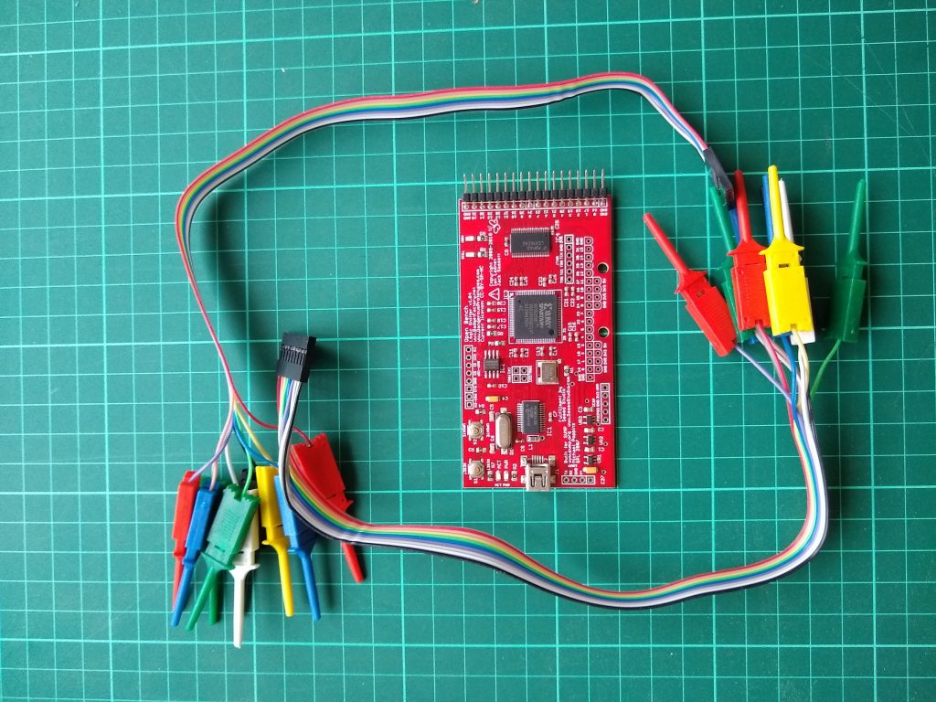
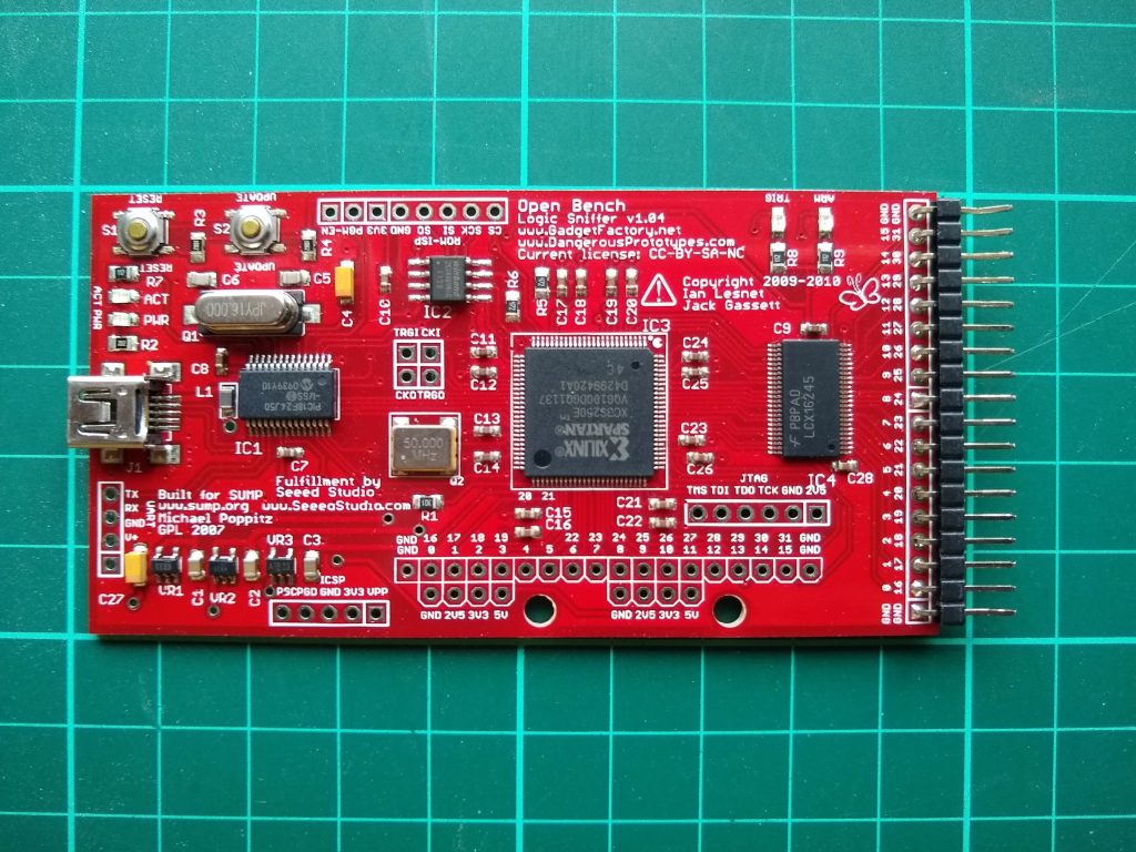
A few months ago I was able to get a bit older piece of hardware for little money, a logic analyzer, the Open Bench Logic Sniffer v1.04. It is based on a FPGA Model of sump.org. It must be from around 2010. I did not know if it still works, but the test cables were worth it. But maybe he is still working and I can use it in future projects?
I googled around a little bit to find the necessary client and finally found it here: gadgetfactory.net. Unfortunately I could not get the client to run under Linux. But for such cases I have a WinXP in a virtual box for some “older” electronic software that has accumulated over time. I used the “initial_install” batch and I could see some reactions. looks good. I could also start the client, but with nothing to measure I saw only a flat line. But now I was confident to have a working device in front of me.
Test Circuit
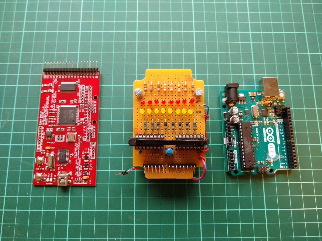
With the help of an Arduino Uno, two 74HC595 some resistors, buttons, LEDs and other small parts from the grab box I could expand one of the Arduino ports to 16bit, fitting the input of the sniffer. It would be very slow but I can check every single input line. the output from. Not in the drawing: The lines between 74HC595 Output and prior resistor will also hooked to the Sniffer input.
BTW – Idea for this circuit and part of the programm (see annex) is from my old Arduino textbook, “Die elektronische Welt mit Arduino entdecken by Erik Bartmann” (see also Erik’s Homepage)
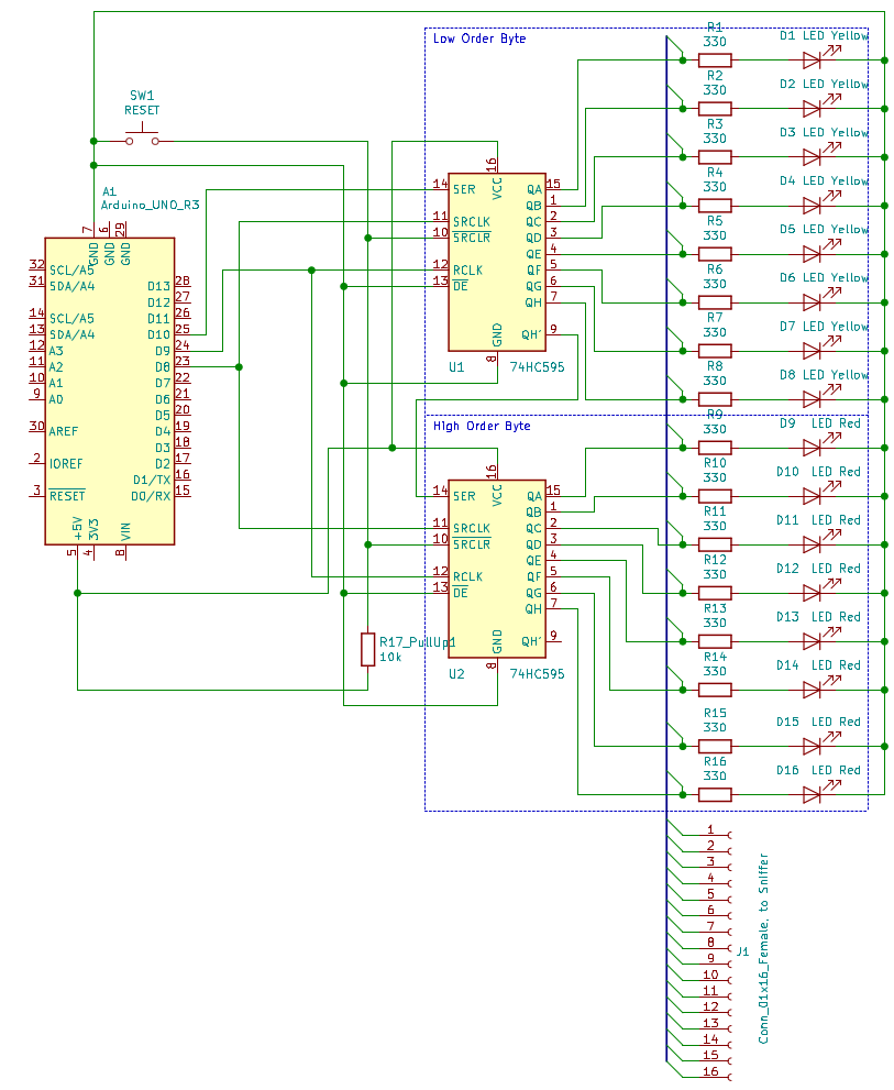 (Link to PDF version: Test_Circuit_-v02)
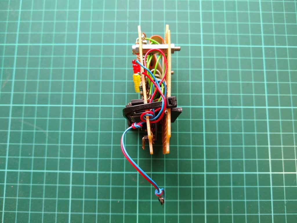
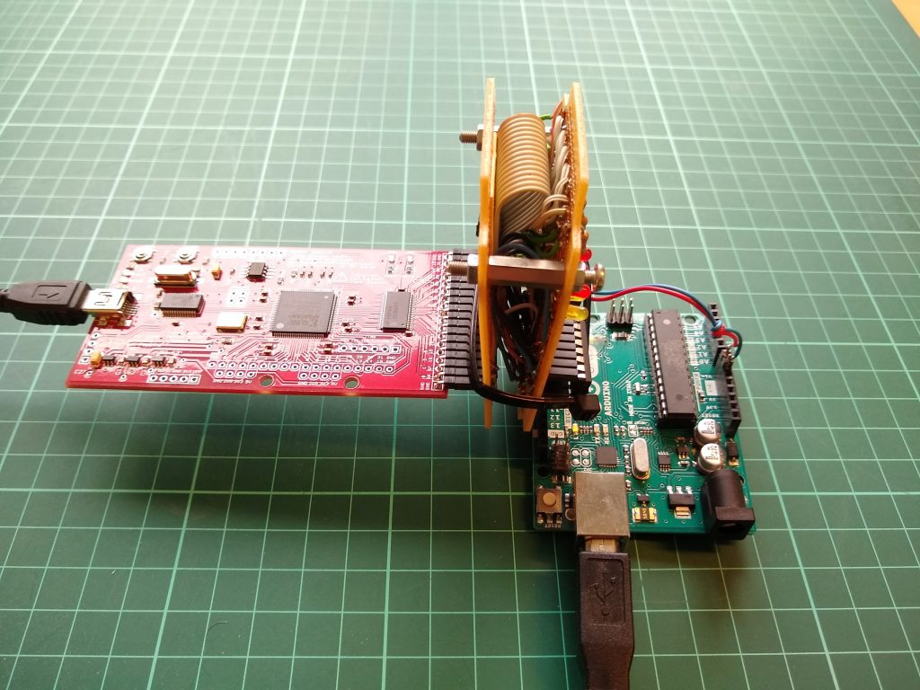
Quickly heated up the soldering iron and threw everything together more or less reasonably:
With all the parts plugged together and a simple Arduino program I could blink the lights right away:
Sniffer Test Output
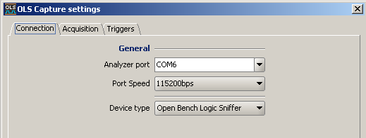
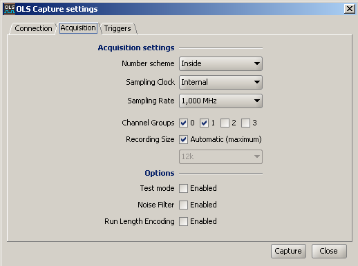
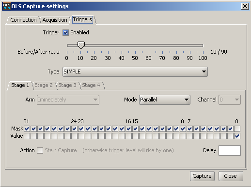
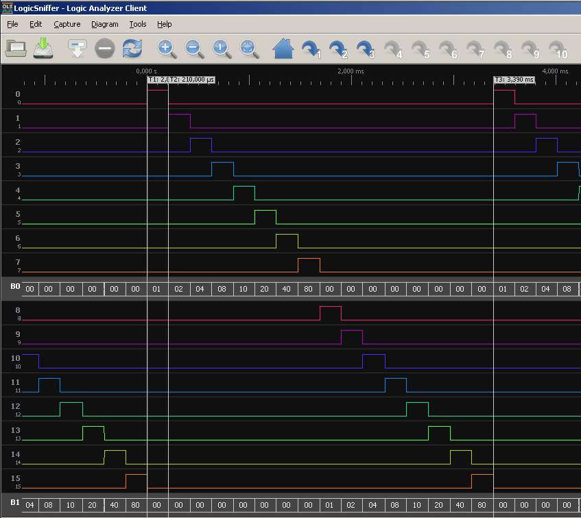
Now the final part. What will I see in the Sniffer Client? With the following settings (in my case COM6, but can different to yours)
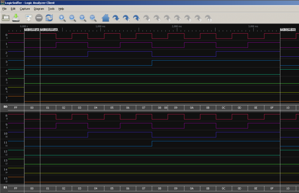
I got this (depending which pattern you activate in the program):
Measurement shows me:
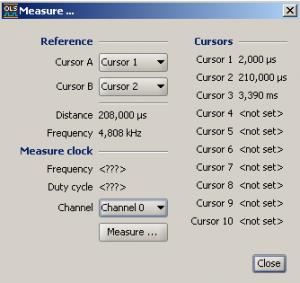
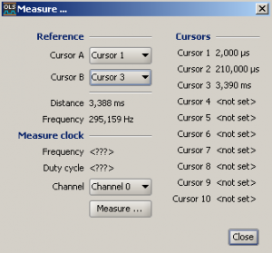
As expected, the test hardware is not exactly the fastest (208µs for each pulse and 3,38ms the whole cycle). In contrast to this, slower is hardly possible. But I can test all 16 channels of the sniffer, which was the goal.
other pattern:
Conclusion
There are certainly currently more powerful Logic sniffers available, even for small money, but this ancestor will certainly be a great help for future projects. Definitely not a bad buy, also because it brought me a few hours of fun.
Annex
File package
Arduino Program
there are different types of pattern you can use, just simply comment out or activate again. with activated Debugging option you will see the pattern on the serial port / terminal.
/*
===========================================================
Test Circuit Programm vor Logic Sniffer
Version : 03
Last Edit: 20.05.2020
===========================================================

by : tgohle (tgohle@googlemail.com)
inspired by: Bartmann, Erik
"Die elektronische Welt mit ARDUINO entdecken"
- Project #7

O'Reilly
ISBN-10 : 3897213192
ISBN-13 : 978-3897213197

*/

// Pattern definieren
// just for playing around...

#define p0 0x0000 // 00000000 00000000
#define p1 0x0001 // 00000000 00000001
#define p2 0x0101 // 00000001 00000001
#define p3 0x8000 // 10000000 00000000
#define p4 0xAAAA // 10101010 10101010
#define p5 0xEEEE // 11101110 11101110
#define p6 0xCCCC // 11001100 11001100
#define p7 0xF0F0 // 11110000 11110000
#define p8 0xF00F // 11110000 00001111

#define DELAY 50 // if needed, delay betwwen Pattern
// Debugging -> use >= 50
// for runtime issues: don't set to 0
// better hide in function "sendByte


word clockPin = 8; // SH_CP
word memoryPin = 9; // ST_CP
word dataPin = 10; // DS
word pattern = p0; // Pattern Variable, predefined with p0000

void setup(){
pinMode(clockPin, OUTPUT);
pinMode(memoryPin, OUTPUT);
pinMode(dataPin, OUTPUT);

// Serial.begin(9600); // serial port for debugging
}

void loop(){

// HW-Debugging - blink all LEDs... 1/2 s on / off
// sendeBytes( p0101); delay(500);
// sendeBytes(~p0101); delay(500);

// for(byte i = 0; i < 16; i++) {
// sendeBytes(p1<<i);
// delay(DELAY);
// }
// sendeBytes( p0); delay(DELAY);
// sendeBytes( p1); delay(DELAY);
// sendeBytes( p2); delay(DELAY);
// sendeBytes( p3); delay(DELAY);
// sendeBytes( p4); delay(DELAY);
// sendeBytes( p5); delay(DELAY);
// sendeBytes( p6); delay(DELAY);
// sendeBytes( p7); delay(DELAY);
// sendeBytes( p8); delay(DELAY);
//
// Test-Pattern 1
// cont lower & high Byte from 0...FF
//
// 0000000000000000 0x0000
// 0000000100000001 ox0101
// 0000001000000010 0x0202
// 0000001100000011 0x0303
// ...
// 1111111111111111 0xFFFF
//
// 1*101 = 101, 2*101 = 202...

for(byte i = 0; i < 256; i++) sendeBytes(p2*i);
// sendeBytes(p0); delay(DELAY); // and back to 0h0000

// Test-Pattern 2
// for(byte i = 0; i < 16; i++) sendeBytes(p1<<i);
// sendeBytes(p0); delay(DELAY); // and back to 0h0000
// and invers...
// for(byte i = 0; i < 16; i++) sendeBytes(~(p1<<i));
}

// send bytes to shift registers
void sendeBytes (word wert){
digitalWrite(memoryPin, LOW);
shiftOut(dataPin, clockPin, MSBFIRST, wert >> 8);
shiftOut(dataPin, clockPin, MSBFIRST, wert & 255);
digitalWrite(memoryPin, HIGH);
// delay(DELAY);
// Serial.println(wert, BIN); // only during Debugging...
}
